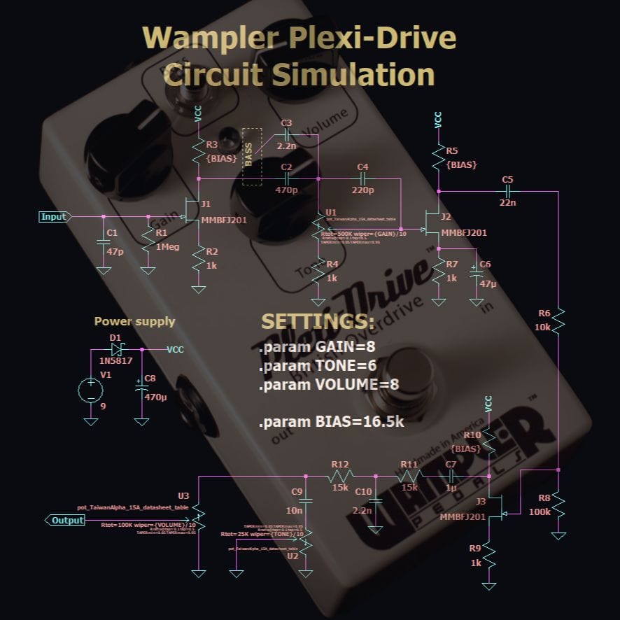
• Intro: The Plexi-Drive is Wampler's take on the cranked vintage Marshall Plexi style pedals. It achieves it's goal to a great extent sound-wise and out of many similar pedals, topology-wise it is the closest to an actual tube guitar amp (stacked JFET gain stages). Since its release, Wampler has released a few variations/revisions of it. This pack simulates the original Plexi-Drive circuit.
• Sound character and intended use: Very tube-like, almost clean on light pickstrokes and progressively saturates as you press harder and harder. It isn't compressed at all like other overdrive pedals on lower gain settings. It can provide a lot of output if needed, enough to push a high headroom clean amp to distortion.
It also features a BASS switch which seems to mimic the impedance interaction between a power amp and a guitar speaker. I did include a few captures with that setting on, but most are without it.
I like to pair this pack with clean to edge of breakup Fender Deluxe or Super Reverb captures. Instantly makes them sound like a Marshall.
It can also be used as a preamp, putting whatever other dirt pedals you want before it.
• Settings: All captures are titled according to the setting positions used.
I covered GAIN settings from 3 to 10 in this pack. This goes from slight crunch to very distorted rock tones.
TONE was set around half-way for most captures. I felt that was the sweet spot for me but if you feel there's lack of tonal options let me know.
The VOLUME was fixed at position 8 for most of the captures, which is well above unity. You are free to adjust the output volume from your NAM host if you need more or less.
If you really want to simulate a faithful output level, I also included a VOLUME sweep response graph at the technical section below.
All knob positions are decimal (not o'clock!).
• Calibration: Calibration metadata is already embedded in the NAM files. You only need to enter the headroom of your audio interface's input in dBu inside your NAM host.
Details: Input: +12 dBu ≘ 0 dBFS | Output: +9.5 dBu ≘ 0 dBFS (for most captures)
Some models were trained at different than +9.5 dBu output level. That's because not all models were trained in one session and I used different values each time for the output. Don't worry, whatever value I used was accounted properly and is correct for each capture.
• Slightly technical info:
(TL;DR: some nerdy stuff, you can skip to notes if you are not interested)
For DIY builds, Wampler himself recommends matching the transistors, so they can be biased using resistors of the same value to maintain the intended frequency response. In the simulation the same J201 transistor model was used obviously, leading to an optimal value of 16.5 kΩ for the BIAS resistors. I believe the original pedal uses 15 kΩ resistors, which is not very far off.
The pedal was simulated with a 9V power supply voltage. 18V is also possible according to Wampler. I would personally also do some re-biasing if I switched to 18V.
All potentiometers in the original are logarithmic (A taper). I derived the values from Taiwan Alpha's 16mm potentiometer datasheet and modeled the 15A taper inside LTspice for the controls.
The circuit was simulated with a speed of ~500ms/s on my computer. Consequently, each simulation with the NAM training wave file took about 7 minutes to complete. That's pretty fast for LTspice standards!
CONTROLS SWEEP GRAPHS (Frequency-gain response): Below you will find graphs showing how the pedal responds to turning each of its knobs/switches. The spectrum is typically from 10 Hz to 25 kHz. A 1 Volt peak AC source was used to generate these graphs. Apart from the swept knob, the other knobs were at noon for these measurements. The frequency range that interests us is from ~80Hz to ~6000Hz for the most part, which is what a typical guitar speaker would produce.
GAIN knob sweep response graph: https://i.imgur.com/R1pHSmo.png
We can see that the pedal gets more mid heavy as we increase the gain. At gain settings below 4 the pedal response is pretty flat.
TONE knob sweep response graph: https://i.imgur.com/jWrF63t.png
Highly adjustable tonal range. Lower settings focus around basses, while higher let a lot of treble content to pass through.
VOLUME knob sweep response graph: https://i.imgur.com/p9nKjge.png
It's a simple voltage divider. The relative frequency response stays practically the same. Only the amplitude changes.
You can use this graph as a reference to add or subtract dB from your output to simulate the VOLUME knob. All captures in this pack were generated with VOLUME set at 8. If for example you wanted to set it at 10 you would add ~4.5 dB, at 5 you would subtract ~12 dB etc. Unity gain is at around position 3.
BASS switch response graph: https://i.imgur.com/iLn9aJS.png
Toggling on the bass switch shifts the bass frequencies lower while also letting more of them pass through. I believe it's aiming to emulate the low-end bump the amp-speaker impedance curve the real amp would produce.
⚠️ Note: These captures are (input AND output) CALIBRATED! Calibrated NAM captures enable you to experience an accurate gain response, similar to the real hardware, or the simulated hardware in this case. Preferably also use an amp capture with calibrated input after them. If you don't know how to set up calibrated NAM chains watch 2dor's tutorials "𝗡𝗔𝗠 𝗰𝗮𝗹𝗶𝗯𝗿𝗮𝘁𝗶𝗼𝗻 & 𝗰𝗮𝗹𝗶𝗯𝗿𝗮𝘁𝗲𝗱 𝗽𝗿𝗼𝗳𝗶𝗹𝗲𝘀: 𝗾𝘂𝗶𝗰𝗸 & 𝗲𝗮𝘀𝘆 [𝟮𝟬𝟮𝟱]" & "𝗦𝘁𝗮𝗰𝗸𝗶𝗻𝗴 𝗰𝗮𝗹𝗶𝗯𝗿𝗮𝘁𝗲𝗱 𝗡𝗔𝗠 (𝗡𝗲𝘂𝗿𝗮𝗹 𝗔𝗺𝗽 𝗠𝗼𝗱𝗲𝗹𝗲𝗿) 𝗽𝗿𝗼𝗳𝗶𝗹𝗲𝘀" on YouTube OR read the "𝗡𝗲𝘂𝗿𝗮𝗹𝗔𝗺𝗽𝗠𝗼𝗱𝗲𝗹𝗲𝗿𝗣𝗹𝘂𝗴𝗶𝗻 𝘃𝟬.𝟳.𝟭𝟮 𝗶𝘀 𝗿𝗲𝗹𝗲𝗮𝘀𝗲𝗱" blog post on the Neural Amp Modeler website.
Of course you are free to experiment! Using the Raw option will also preserve the unit's output that is relative to your input signal or just use whatever levels you like more! The calibrated options will just give you the results that are closest to real life.
⚠️ Note 2: These captures are NOT derived from the physical hardware but from circuit simulation done in a SPICE environment. I try to make this very clear in my titles, descriptions and thumbnails so that I don't mislead any people. Of course that doesn't mean they can't sound just as good, provided they are done correctly. From my tests, where I compared other physical circuits to their SPICE simulated ones I couldn't hear any difference, other than what could be attributed to component tolerances. I can't say the same for commercial plugin versions of those circuits that I've tried.
Some added bonuses of SPICE simulated gear is that component self-noise is usually not simulated, which results in better ESR results, and also that we can capture just the intended circuit and not a chain consisting of unrelated devices like DIs, Reamp boxes, audio interface preamps etc. which imprint their own character to the signal.